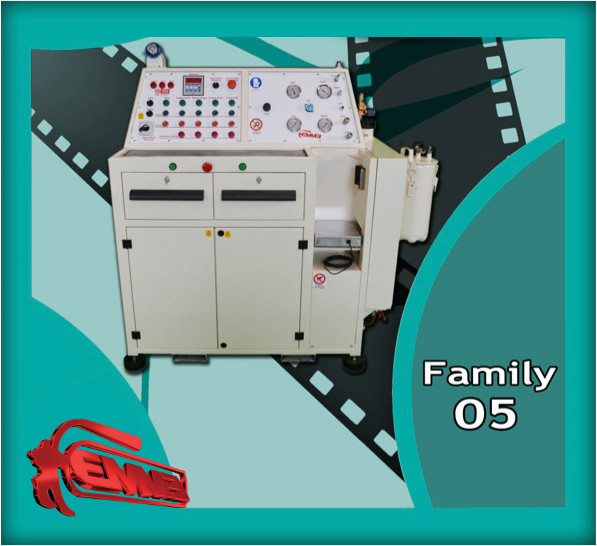
Family 05
Biography
Ever since the 1992 UNI9994 norm was in effect, the Emme antincendio company was always remarkable, delivering excellent service quality, pledging themselves to refine the customer relationships pursuing innovations and solutions that can be kept up to date with the changing market conditions. In 1998 the idea of Family 05 was born, at that time such an equipment that enabled the maintainers to effectuate the due operations in specific machines respecting the norms wasn’t commercially available yet. In addition it was impossible to effectuate such as certain types of on-the-spot checks inspection procedures, meaning from the costumers it-self. All the equipment existing were bulky, and of various kinds. There is the reason why Gian Franco Milli created a machine so it could be installed directly on the maintainers vans and able to effectuate any kind of control just as the normative required, and that would replace all the devices on the selling available at that time, an all-in inclusive machine by which was possible to do home delivery. The idea was not restricted to the water performance of powder extinguishers CO2, foam and gas, but also the withdrawal, performance control and dry water performance control of the UNI 25-45-70 fire hoses. To summon a complete and unique machine that would revolutionize the world of maintenances.
The first prototype was realized and patented designed in 1998, the machine was already grooved really compact and able to effectuate a wide range of operation in a simple manner, but after some years the final addictions were made, both in the mechanical and aesthetic point of view, until the definitive version was reached in 2009. The Family 05 remained unchanged until recently, this is a merely aesthetic carpentry restyling that made the machine good-looking.
The Family 05 is a really compact device that can also be installed in the company, but it also lends itself to be installed in the classic maintainer’s vans and even on smaller vehicles, thanks to the reduce dimensions and its strong carpentry. With its functions versatility and variety allows to the users to lessen considerably the costs and the rising of the service efficiency, in fact it embodies the operational capacities of 8 old-designed devices and lessen considerably the investment amount for the maintenance companies.
 Why it was named FAMILY05 ?
The name has two reasons. First, the Milli family is composed by 5 people Gian Franco, Adriana, Barbara, Marco, Alberto…So it expresses the wide energy of 5 people. The second reason is that in the Family 05 5 essential elements are present
The vacuum pump, the water pump, transfer pump, of liquid CO2 , the air compressor and the pneumatic clamp electronic scale.
THECNICAL DATA
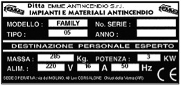
The device is distinguished from the dimpled name on the metallic label, located on the loom side part.

|
DIMPLED NAMES ON METALLIC LABEL DESCRIPTION
|
|
MODEL
|
Machine model
|
|
Serial n.
|
Serial number
|
|
TYPE:
|
Device type
|
|
Year
|
Year of manufacture
|
|
MASS
|
Device weight Kg
|
|
POWER
|
Kw Machine Power
|
|
ALIMENTATION
|
Alimentation tension
|
|
VOLT
|
Alimentation tension
|
|
AMPERE
|
Electric power
|
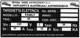
The machine is also marked from a plate reporting the electronic characteristic of the power cabinet. The target is placed internally to the power closet.
|
DIMPLED NAMES ON METALLIC LABEL DESCRIPTION
|
|
Provider
|
Rerence Code of the device
|
|
Serial n.
|
Serial number
|
|
Un
|
Rated actuating voltage and number of procedural steps
|
|
f
|
Hz electrical frequency
|
|
In
|
Full-load current
|
|
II max
|
Rated current max of the highly-loaded
|
|
Icu
|
Switching capacity short circuit
|
|
Distinction code
|
Electrical components description code
|
|
Year
|
Transformer/rectifier year of construction
|
FAMILY 05
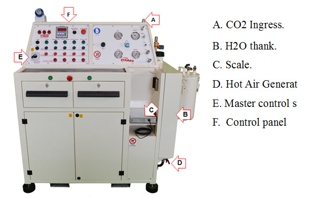
The device operating principle is based on a range of interventions to effectuate on various kind of extinguisher. To effectuate these interventions, some unique-plant alone working units were built, each one with a specific thask.
All the working units lead a control that inspect the different operative procedural steps of the device.
Working unit’s development and regulation are run from the electric panel trough a PLC that allows to draw up the device according to the various mansion to effectuate on each extinguisher.
The FAMILY 05 is a device designed and implemented to effectuate the fire extinguishers performance control and inspection according to the UNI 9994-92 * norm prescription.
The device allows the following operations:
CO2 extinguishers refill:
- piston pump usage to decant the liquid high or low pressure fire-extinguishing medium(from thank to thank and from storage tank to reservoir
ABC powder fire-extinguisher refill:
- vacuum pump usage, protection filters provided, to the powder pouring in charging and emptying operations (the latter provides for the aid of an apposite container).
Water performance control:
- using water to verify the fire extinguisher thank stability with a during 30 seconds water performance to a maximum pressure value hallmarked on the thank itself.
* UNI 9994-1 : 2013 NORM PROVIDE EXTRACT:
Application and field requirements
This standard lays down the initial check criteria, the surveillance, the period performance control the scheduled review, and the fire-extinguishers performance control to safeguard the operative efficiency.
The rule applies for the ordinary and extraordinary wheels and portable fire-extinguishers maintenance, fire-extinguishers and fires of class D, does not apply for the fire- extinguishers installation activities.
References
UNI 8633 Pressure gauges , vacuometers pressure/Vacuum gauges with spring elastic element. Acceptance and performance control technical units
UNI 9492 Wheel Fire-extinguishers - Building and testing techniques requirements
UNI EN 341 Fire-fighting , Portable fire extinguishers
Expected life lasting description testing the effectiveness
UNI EN 342 Fire-fighting , Portable fire extinguishers (tightness, dielectric test, compaction test, special disposition)
D.P.R nr. 524 8 June 1982: Effective Implementation nr. 77/576/CEE for the approximation of the laws, regulations and administrative provisions of the Member States concerning health and safety requirements at the workplace, and of the nr. 79/640/CEE Directive amending the annexes of the former regulation.
Terminology
For the purposes of this rule the following definitions apply:
- Extinguishers: a device containing a fire-extinguisher medium that can be projected and orientated on a fire under the action of an internal pressure.This pressure can be provided from a permanent prior compression, from a chemical reaction or from an auxiliary
- gas realease (UNI 9492 e UNI EN 3/1 conform definition)
- Portable extinguisher: extinguisher designed to be portable and hand-held and ready-to-use. Lower or equal to 20 kg mass ( UNI EN 3/1 conform definition)
- Wheel extinguisher: fire-extinguisher carried on wheels, total mass higher than 20 kg and fire-extinguisher medium content around 150 kg (UNI 9492 conform deifinition )
- Fire-extinguisher agent: all the products/ the product contained in the fire-extinguisher that help fire-fighting (UNI 9492 and UNI EN 3/1 conform definition)
- Charge for an extinguisher: fire-extinguisher medium contained in the fire-extinguisher mass or volume. From a qualitative point of view the devices water based charge is expressed in volume (litres) and all the other devices in mass (kg), UNI EN 3/1 conform definition.
- Approval: Type approval technical administrative procedure by wich the fire-extinguisher prototype is tested, the rule consistency certified, the competent authorities have issued an order allowing the prototype reproduction before marketed.
- Producer: whoever produce, assemble, and places on the market the full-complete fire-extinguisher and ready-to-use.
- Maintenance technician: any specialized natural or legal person authorized to fulfil the fire-extinguisher maintenance service.
- Maintenance tags: document showing the effectuated intervenctions according to the regolation.
Classification
Depending on the fire-extinguisher medium the extinguisher fall into these cathegories :
- water extinguishers;
- foam extinguishers;
- powder extinguishers;
- (CO2) Carbon dioxide extinguishers;
- halogenated hydrocarbon extnguishers.
|
TECHNICAL DATAS
|
|
MODEL
|
FAMILY 05
|
|
Total encumbrance dimensions (LxPxH)
|
1212 mm x 580 mm x 1320 mm
|
|
Worktop dimensions (LxP)
|
840 mm x 227 mm
|
|
Worktop height (H)
|
977 mm
|
|
Pneumatic pressure bar locking system high rate
|
200 mm
|
|
Weight ( total mass)
|
Around 280 kg.
|
|
Alimentation
|
220 Vca - 50/60 Hz - 16A
|
|
Power absorbed
|
Max 3 KVA
|
|
Max noise level
|
70 dB
|
|
Max filling speed
|
Powder:
3 kg/min.
|
Carbon dioxide(CO2):
2,5 kg/min.
|
|
Performance control speed
|
Around 1,5 min. to reach 3,5 Mpa
|
Machine Safety standard regulations list
The machine was implemented according to the following safety regulations as they can represent, resulting from the CEN committee’s work, the highest safety level.
-
98/37/CE Regulation known as “Machine Safety Regulation”
-
2006/95/CE Regulation Low voltage (DBT)
-
89/336/CEE Regulation about the Electromagnetic Compatibility (EMC)
-
93/68/CEE Regulation modifies the 89/336/CEE regulation about the CE marking
-
EN 12100-1 Machine safety – Fundamental concepts, general principles for the design
Part I: Terminology, basic methodology.
Part 2: Specifics and technical principles.
- EN 294 Machine safety – Safety of machinery < Safety distance to prevent danger zones being reached by the higher limbs.
- EN 349 Safety of machinery - Small openings to avoid crushing of parts of the human body
- EN 414 Safety of machinery – Establishing the rules governing the writing and drawing up of safety regulations.
- EN 418 Safety of machinery – Emergency stop, functional aspects. Principles of design.
- EN 626-1 Safety of machinery – Reduction of health-related risks, resulting from the machine’s discharges of hazardous substances.
Part 1 – Principles and specifics for machine builders.
- EN 626-2 Safety of machinery – Reduction of health-related risks, resulting from the machine’s discharges of hazardous substances
Part 2 – Methodology leading to verification procedures.
-
EN 953 Safety of machinery - General requirements for the design and construction of of fixed and movable guards.
-
EN 981 Safety of machinery – System of auditory and visual danger and information signals.
-
EN 1037 Safety of machinery – Insulation and energy loss – Prevention of unexpected power-up.
-
EN 1050 Safety of machinery – Principles for the assessment of risks.
-
EN 1088 Safety of machinery – Interlocking devices associated with guards.Design and choice principles.
-
EN 9432 Acuostic. Determine personal noise exposure levels and the noise of the working environment.
-
EN 11200 Acuostic. Noise emitted by machinery and equipment. Guidelines for the use of basic standards for the determination of emission sound pressure levels at a work station and at other specified positions.
-
EN 11202 Acuostic. Noise emitted by machinery and equipment. Measurement of emission sound pressure levels at a work station and at other specified positions. Up warded control method.
-
EN 60204-1 Safety of machinery - Electrical Equipment for Machinery
Part 1: General requirements
- EN 60439-1 Low-voltage switchgear and control gear assemblies (low-voltage boards)
Part 1: Type-tested and partially type-tested assemblies.
- EN 60529 Degrees of protection provided by enclosures ( IP Code ).
- EN 60947-4-1 Low voltage controls and switchers.
Parte 4: Hard-contact switches and motor controllers .
- EN 60947-5-1 Low voltage controls and switchers.
Part 5: Electromechanical control circuit devices and switching elements .
Part 1: Electromechanical control circuit devices.
- UNI EN ISO 13849-1 Safety of machinery – Safety related parts of control systems.
Part 1: General principles for the design.
- EN 983 Safety of machinery – Safety related requirements for fluid power systems and their components. Pneumatic.
Dangerous zones
There are no zones in which the operator may run high risk of accidents
Referring to the (3.1 Pic), the dangerous zones are appropriately protected from the safety devices, are listed and located :
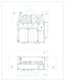
Pic. 3
-
Forward area (Pic.3-1) Related to the loading and downloading time of the envelope or of the extinguisher in pneumatic locking compartment: body crushing danger, shearing danger, to-load objects falling danger, (evelope or extinguisher, transferring material dropping (water or dust), threats.
-
Right side (Pc.3-2) ) Related to the loading and downloading time of the envelope or of the extinguisher in pneumatic locking compartment: body crushing danger shearing risk, jets of hot air from the industrial ventilator located in the lower.
-
Behind area (Pic.3-3) Maintanance and regulation of the machining heads integrated in the machine wall related: shearing risk, entanglement, variable fluid pressure jets.
-
Left side(Pic.3-4) Maintanance and regulation of the machining heads integrated in the machine wall related: shearing risk, entanglement, variable fluid pressure from various curcuits jets.
-
Load and download compartment (Pic.3-5) of the envelope or extinguisher to treat: body crushing danger, shearing danger to-treat objects falling, (evelope or extinguisher.
-
Panel of the electrical board and control console zone (Pic.3-6): risk of receiving a life-threatening electric shock in case of contact with live parts.
-
Pressure control and quick disconnect zone. (Pic 3-7): pressure pipe jacking.
SAFETY DEVICES
The machine satisfies all the Machinery Directive requirements related to the current principles of safety integration.
Referring to the (Pic. 4) the risk of accident prevention measures have been implemented in the various machine zones.
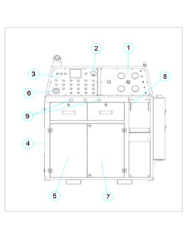
Pic. 4
-
Two-hand control: (Pic 4-9) to activate the envelope or extinguisher lock function, in the treatment chamber; the operator after locating the object that is to be treated in the locking compartment. Switches simultaneously the two- switches.The pneumatic clamp (Pic 4-8) blocks the object to be treated, keeping the operator hanging around in a shearing and body crushing safe zone.
-
Side movable guards (left side): located to protect the side access to the moving parts interlocked by safety microswitch; the removal of the guards is possible only with a voluntary transfer that stops the machine. (Pic. 4-4)
- Front movable guards: located to protect the front access to the moving parts and interlocking with safety microswitch. The access inside the compartment where the machining heads are located is secured by the total absence of electrical energy and so it is impossible to have moving parts. (Pic. 4-5,7)
- Fixed guards of moving parts: additional fixed guards were implemented on moving bodies (pulleys, gears, moving belts, ecc…) located inside the machining heads compartment.
- Back fixed guards: located to protect the machining head compartment so that they can avoid to be entered to the moving mechanical parts. The protection is realised in an appropriate thickness steel sheet strongly screwed to the machine’s carpentry. On the carter are attached some labels indicating the interdiction to the zone when the machine is electrically fired.
- Fixed guard on pneumatic clamp: located to the protection of the shearing due to the reciprocating cylinder movements.( Pic. 4-8)
For service purposes that require the fixed guards removal is under the obligation to isolate the machine from the electricity grid opening the master control switch located on the machine’s frontal part. When the intervention is finished re-engage the guards in the previous operational conditions in order to avoid accidents risk.
-
Central cabling cabinet: the cutting master control switcher of the machine from the power line shutters down the overall machine. On the switchgear some labels are describing the electrical voltage related risks. (Pic 4-3)
-
Various fluid circuits: the circuits are built with working pressure suitable pipework. Control-circuits, according to the regulations, are low-voltaged made. (24 Vcc) (Pic. 4-1)
RESIDUAL RISKS
The simple possible residual risk warning is not acceptable in case that risk could be eliminated with safety devices. The residual risk’s list can be related to the misuse of operations that weren’t made following this manual:
- Pneumatic or hydraulic circuit and other machining head’s curcuits mounted on the machine , maintenance operations related. Possible fluids projection if not discharged the circuits before operating is a risk.
-
Adjustment operations related: of the related arrangements involved in the machining head group if the safety measures to operate inside the machines compartment are not adopted.
-
Related to the maintenance operations on the electrical system if the machine is not correctly isolated. Risk of contact with operating devices whenever operating without isolating the machine from the firing power line. Apposite labels on the switchgear warns the risk and interaction on operating devices.
SAFETY NOTES
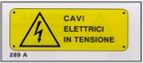
On the machine are located signs to warn the operator of the possible danger existing in that zone.
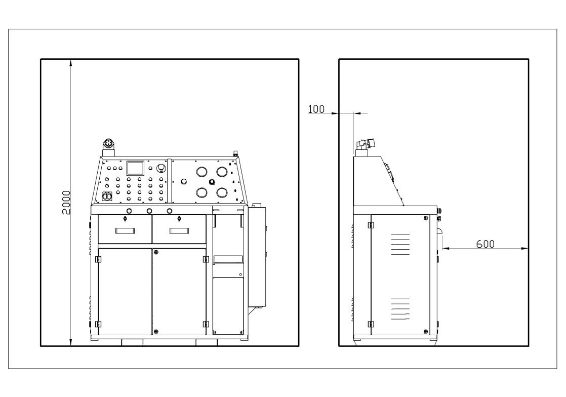
DIMENSIONS
The device is not cumbersome and does not present geometric outlines than needs no special adjustments.
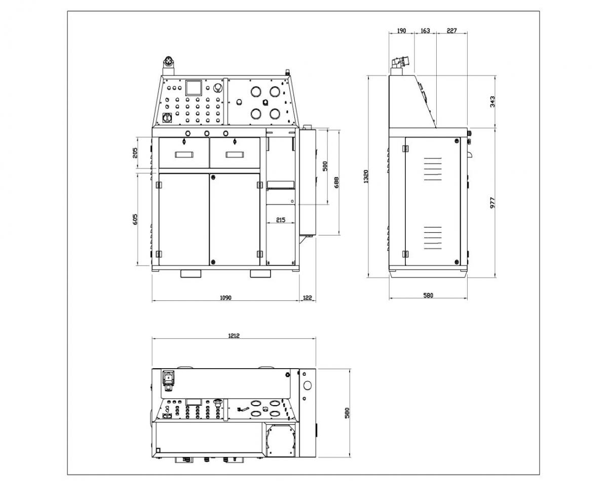
Pic.5
FOOTPRINT AREA
The machine is to be installed in such a way that a sufficient area to enable the moving and use of the material to be machined is leaved around.
In the picture are drawed the minimum installations for the normal use and maintenance operations.
NEXT PAGE >>>